Report and its Configuration Command
As mentioned earlier, ‘Report’ refers to the frame that the terminal device actively generates and sends to the backend server when it reaches certain established conditions. And some conditions can be changed by configuration commands.
In order to reduce the frame size and increase the effective usage rate of the wireless traffic, all report frames are uniformly encoded to Binary frames. And the big-endian byte order is used for the transmission of multi-byte data types (int, float, double, etc.). For example, for the integer 305419896 (i.e., 12345678H), the byte 12H will be sent first, and then 34H, 56H,78H.
In order to facilitate the backend server to parse the report frame, this protocol limits the maximum length of a single report. Usually the maximum length of a report cannot exceed 1440 bytes. When the length of the original report is too long, the terminal will automatically split it into multiple reports.
Usually user data is contained in ‘Records’, and a report can contain multiple records. The whole frame format of the report is as follows:
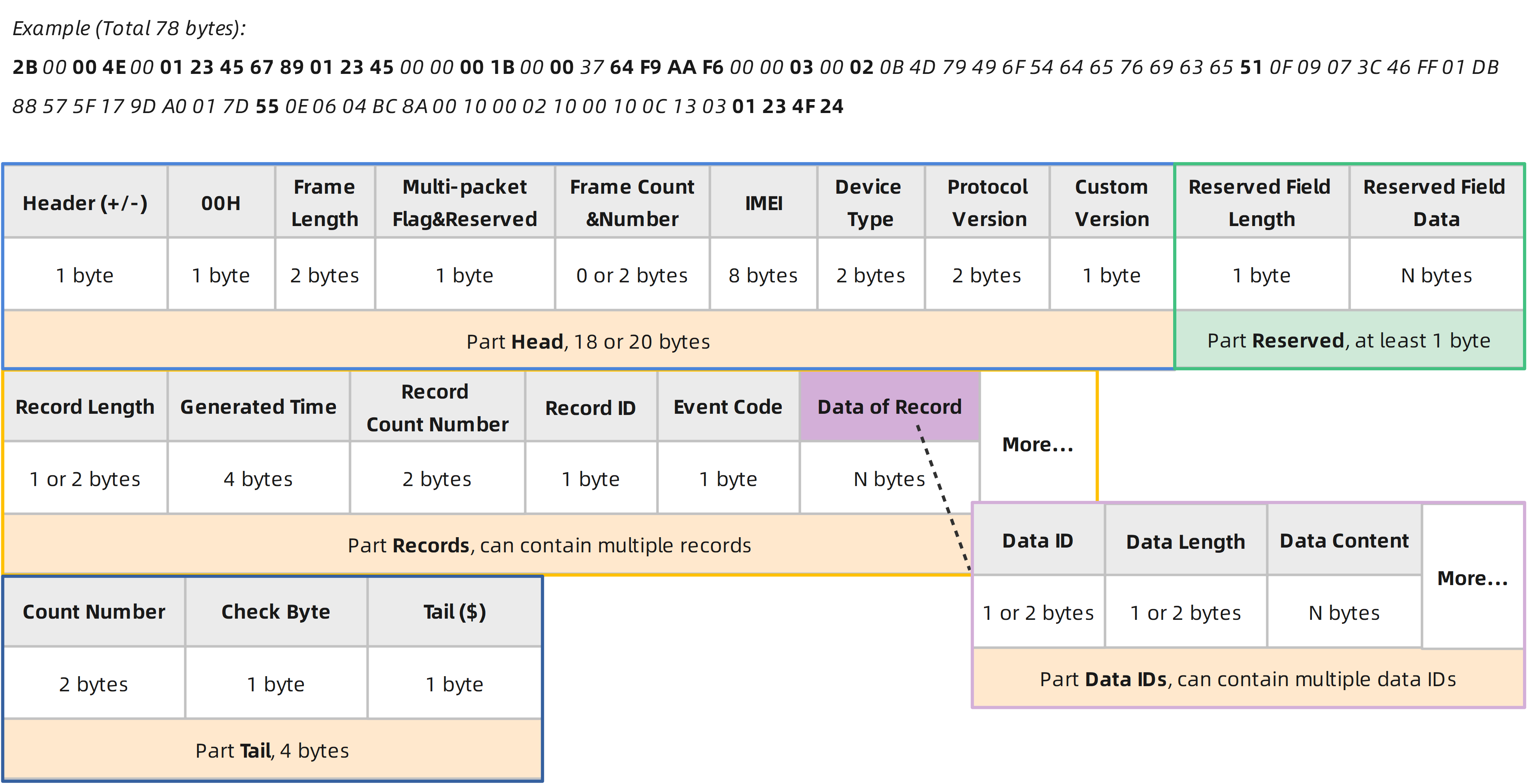
Example (Total 78 bytes):
2B 00 00 4E 00 01 23 45 67 89 01 23 45 00 00 00 1B 00 00 37 64 F9 AA F6 00 00 03 00 02 0B 4D 79 49 6F 54 64 65 76 69 63 65 51 0F 09 07 3C 46 FF 01 DB 88 57 5F 17 9D A0 01 7D 55 0E 06 04 BC 8A 00 10 00 02 10 00 10 0C 13 03 01 23 4F 24
Parts |
Fields |
Length (Byte) |
Range/Format |
Default |
|
|---|---|---|---|---|---|
Head |
Header |
1 |
2BH (+) or 2DH (-) |
2BH (+) |
|
00H |
1 |
00H |
00H |
||
Frame Length |
2 |
||||
Multi-packet Flag & Reserved bits |
1 |
00H or 80H |
|||
Frame Count & Frame Number |
0 or 2 |
Present when ‘Multi-packet Flag’ is 1 |
|||
IMEI |
8 |
||||
Device Type |
2 |
0000H-FFFFH |
C031H |
||
Protocol Version |
2 |
0001H-FFFFH |
000AH |
||
Custom Version |
1 |
00H-FFH |
00H |
||
Reserved |
Reserved Field Length |
1 |
00H-FFH |
00H |
|
Reserved Field Data |
N |
||||
Records |
Record Length |
1 or 2 |
00H-7FH or 8080H-FFFFH |
||
Generated Time |
4 |
||||
Record Count Number |
2 |
0000H-FFFFH |
|||
Record ID |
1 |
00H-FFH |
|||
Event Code |
1 |
||||
Data of Record |
Data ID |
1 or 2 |
00H-7FH or 8080H-FFFFH |
||
Data Length |
1 or 2 |
00H-7FH or 8080H-FFFFH |
|||
Data Content |
N |
||||
… |
|||||
… |
|||||
Tail |
Count Number |
2 |
0000H-FFFFH |
||
Check Byte |
1 |
00H-FFH |
|||
Tail |
1 |
24H ($) |
24H ($) |
||
Header
1 byte. 2BH (ASCII character ‘+’) or 2DH (ASCII character ‘-‘):
2BH indicates Real-time Report, which is sent successfully in time.
2DH indicates Buffer Report, which is not sent successfully in time.
For more information, please refer to Report Priority and Buffer Report below.
00H
1 byte. Always 00H. Used as an identifier.
Frame Length
2 bytes. The length of this message from ‘Header’ (2BH or 2DH) to ‘Tail’ (24H).
For example, 0136H represents 310 bytes.
Multi-packet Flag & Reserved bits
1 byte, the highest bit (bit7) is ‘Multi-packet Flag’, which is used to indicate whether this report contains the ‘Frame Count & Frame Number’ field: 0b0 means no, and 0b1 means yes.
The lower 7 bits of this byte are reserved.
Frame Count & Frame Number
2 bytes. The first byte means ‘Frame Count’ and the second byte means ‘Frame Number’.
When the length of the message is too long, the terminal will automatically split it into multiple reports for sending. The ‘Frame Count’ represents the number of reports obtained by dividing the message, and the ‘Frame Number’ is a numeric to indicate the sequence of the current report.
Please note that the report contains these two bytes only if ‘Multi-packet Flag’ is 0b1 and not so if it is 0b0.
IMEI
8 bytes. The International Mobile Equipment Identity of the terminal device.
For example, 0123456789012345H indicates IMEI “123456789012345”.
Device Type
2 bytes. The device type refers to the terminal model.
For GL601, it is C031H, i.e. “C031”.
Protocol Version
2 bytes. The version number of this @Track protocol.
For example, 0001H means V1, 000CH means V12, and 007BH means V123.
Custom Version
This version number is reserved for user customization.
For example, 01H means V1, 0CH means V12, and 7BH means V123.
If the custom version number has not been set, it defaults to 00H.
Reserved Field
1+N bytes. The reserved field is reserved for extended use. The first byte is ‘Reserved Field Length’, it indicates the number of bytes occupied by ‘Reserved Field Data’.
In particular, if ‘Reserved Field Length’ is 00H, the ‘Reserved Field Data’ is absent.
Note
In order to improve compatibility, the parser should decide how many bytes to skip to locate the next field based on the value of ‘Reserved Field Length’.
Records and Data IDs
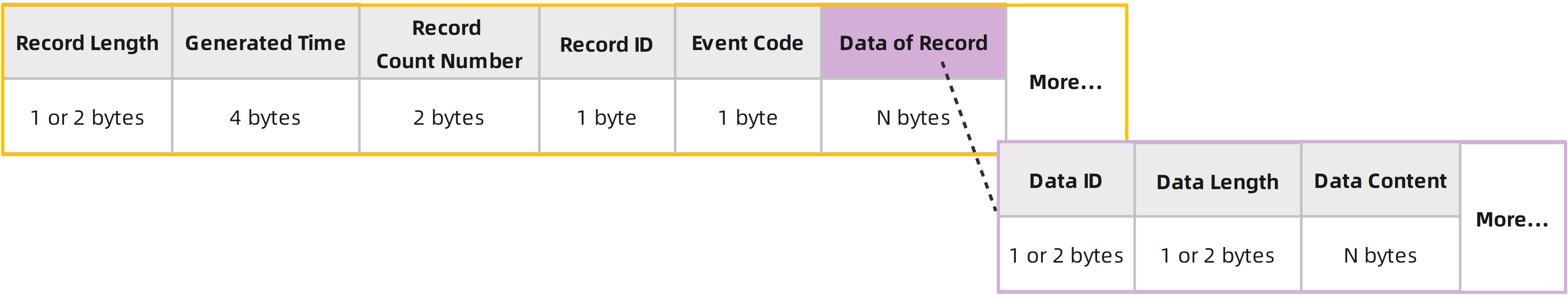
In a report, user data is always organized into records for transmission. Records are always made up of ‘Record Length’, ‘Generated Time’, ‘Record ID’, ‘Event Code’ and ‘Data of Record’ as described below.
Note
A report can contain multiple records, which are next to each other, and the parser can locate the beginning of the next record through the ‘Record Length’ field.
Record Length
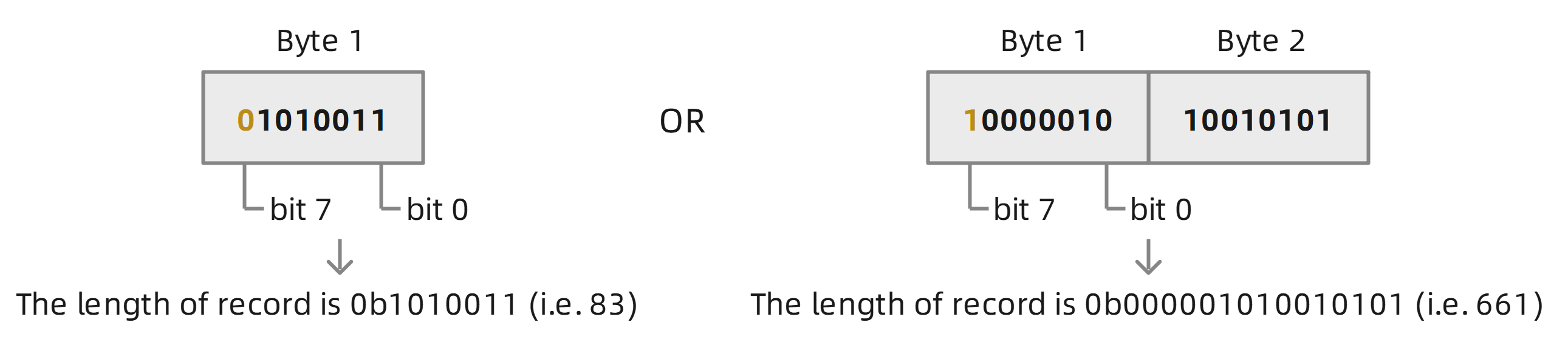
1 or 2 bytes. The number of bytes occupied by the entire record, including ‘Record Length’ itself.
The highest bit of 0 means that ‘Record Length’ occupies only 1 byte, and the value is represented by the lowest 7 bits; The highest bit of 1 means that ‘Record Length’ occupies 2 bytes, and the value is represented by the lower 7 bits of the first byte and the second byte. Please see below:
Generated Time
4 bytes. The time when the record was generated, difference, in seconds, between the UTC time and midnight, January 1, 1970.
For example, 64F9AAF6H (i.e., 1694083830) indicates the UTC time September 7,2023,10:50:30.
Record Count Number
2 bytes. A self-increasing count number in each record, it begins from 0000H and increases by 1 for each record, and it rolls back after FFFFH.
The record count number is accumulated according to the records are generated. After the terminal is restarted, the record count number will continue to accumulate based on the count before restarting.
Record ID
1 byte. In general, the record ID always corresponds to a specific event, such as the event of entering or exiting the Geo-fence, the event of reporting the location of terminal periodically, and so on. In other words, record ID can indicate why the record was generated.
Please refer to Records for the record IDs supported by the terminal device.
Event Code
1 byte. The event code is used to indicate the specific reason for the record to be triggered, it is determined by the specific record ID, that is, the same event code may have different meanings for different record IDs.
The event code is defined in each record ID, please refer to Records for detailed definition.
Data of Record
The specific format of ‘Data of Record’ is as follows:
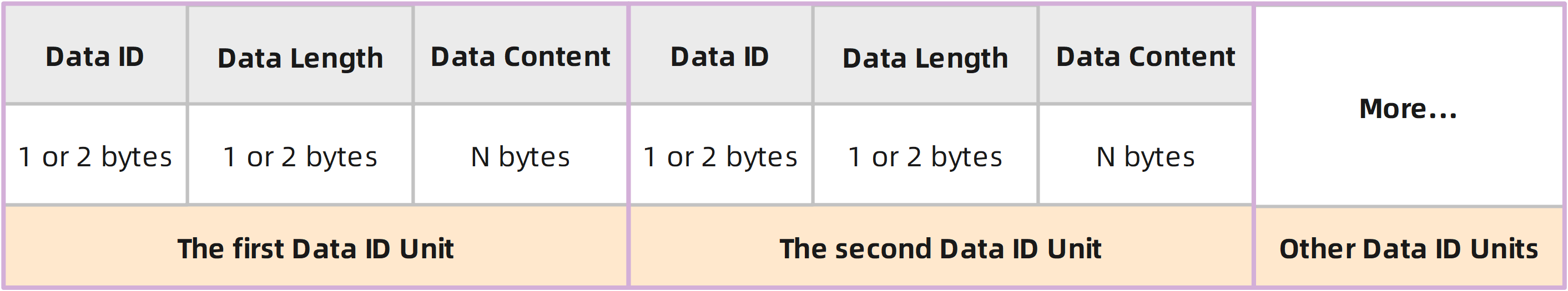
The ‘Data of Record’ consists of one or more Data ID units, and each Data ID unit contains three parts: ‘Data ID’, ‘Data Length’, and ‘Data Content’.
Data ID
This protocol assigns a unique ID to all information that needs to be sent to the backend server. Some information items are closely related to each other and always are transmitted in one piece, they also have a unique ID. These unique IDs are called Data IDs. In other words, a data ID can contain only one piece of indivisible information such as Device Name, or multiple information such as Longitude and Latitude.
The data ID is represented by 1 or 2 bytes. Same as ‘Record Length’ mentioned above, the highest bit of 0 means that ‘Data ID’ occupies only 1 byte, and the value is represented by the lowest 7 bits; The highest bit of 1 means that ‘Data ID’ occupies 2 bytes, and the value is represented by the lower 7 bits of the first byte and the second byte.
Please refer to Data IDs for the data IDs supported by the terminal device.
Data Length
Length of content of Data ID. The actual length of the information represented by the data ID, occupying 1 or 2 bytes. Same as ‘Record Length’ mentioned above, the highest bit of 0 means that the length occupies only 1 byte, and the value is represented by the lowest 7 bits; The highest bit of 1 means that the length occupies 2 bytes, and the value is represented by the lower 7 bits of the first byte and the second byte.
Note
If the ‘Data Length’ is equal to 00H, it means that the terminal device cannot obtain the content of the ‘Data ID’ when the ‘record’ is generated, or the data ID is a special ID, which is only meaningful in a specific record (this will generally be mentioned in the definition of data ID). When ‘Data Length’ is 00H, the ‘Data Content’ field will be absent.
Data Content
The information represented by the data ID, its meaning is determined by ‘Data ID’, and the length is indicated by ‘Data Length’.
Please refer to Data IDs for the data IDs supported by the terminal device.
The tail part of report contains three fields ‘Count Number’, ‘Check Byte’, ‘Tail’, as follows:
Count Number
2 bytes. A self-increasing count number in each report frame, it begins from 0000H and increases by 1 for each report frame, and it rolls back after FFFFH.
The count number is accumulated according to the order in which the reports are sent, not in the order in which the reports are generated. After the terminal is restarted, the count number will continue to accumulate based on the count before restarting.
Note: If you find that the count numbers of the received reports are not consecutive, a possible reason is that the terminal has successfully sent the missing report but it was lost during network transmission or discarded by the backend server.
Check Byte
1 byte. This is an 8-bit CRC checksum, it is generated by a CRC algorithm with the properties displayed in CRC-8 Calculation below. The CRC covers the content of ‘Header’ to ‘Count Number’.
Tail
1 byte. 24H (ASCII character ‘$’).
Here is an example of parsing the report frame.
Report Priority and Buffer Report
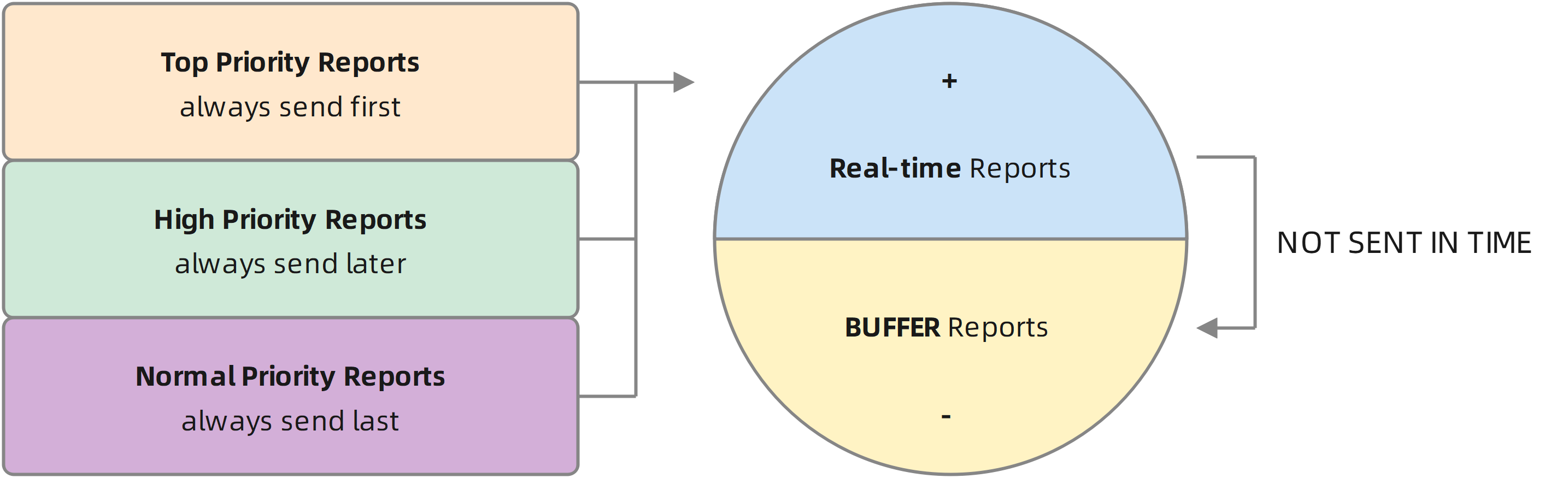
Reports have three priorities: Top, High and Normal.
The terminal device always sends the top-priority reports preferentially, regardless of whether their generated time is before or after the high-priority and normal-priority reports. When there are many top-priority reports, they are sent in the order of the generated time.
Similarly, after sending top-priority reports, the terminal device always sends the high-priority reports preferentially, regardless of whether their generated time is before or after the normal-priority reports. When there are many high-priority reports, they are sent in the order of the generated time.
By default, the normal-priority reports are sent in the order in which they are generated, unless the terminal device is set to send real-time reports preferentially in the AT@RPS command.
If there is no cellular network signal around or the signal is very weak, the reports will not be sent to the backend server in time, and they will stay in the terminal device until the surrounding cellular network signal is strong enough for they can be sent to the server.
To distinguish between the newly generated reports and the reports generated earlier, the reports that are successfully sent in time are called Real-time reports, and the reports that have not been sent successfully in time are called Buffer reports. The header of the real-time report is represented by character ‘+’ (2BH), and the Buffer report is represented by character ‘-’ (2DH). In other words, the report with the header ‘-’ should be sent to the backend server at an earlier time.
All priority (Top, High, Normal) reports may become Buffer reports; and the AT@RPS command can set real-time reports to be sent first, which is only valid for reports with Normal priority.
Top and High Priority Reports list
The following are top and high priority reports supported by GL601:
Top-priority Reports
High-priority Reports
Normal-priority Reports
The reports not mentioned above are all normal-priority reports.
CRC-8 Calculation
The 8-bit CRC checksum in the report should be calculated according to the properties in the table below:
Example:
CRC (2B 01 23 45 67 89 01 23 45 FE 01 06 01 02 01 FF 5D B3 8C 80) = FEH (0xFE)
Property |
Value |
|---|---|
Name |
CRC-8 |
Width |
8 bits |
Polynomial |
0x31 (X8 + X5 + X4 + 1) |
Initialization |
FFH (0xFF) |
Reflect input |
False |
Reflect output |
False |
Final XOR |
00H (0x00) |
Here is a corresponding CRC-8 algorithm routine written in C language:
#define CRC_POLYNOMIAL 0x131 // P(x) = x^8 + x^5 + x^4 + 1 = 100110001
unsigned char crc8_calc(unsigned char data[], unsigned int n) {
    unsigned char crc = 0xFF; // calculated checksum
    unsigned char bit; // bit mask
    unsigned int i; // byte counter
    for (i=0; i < n; i++) {
        crc ^= (data[i]);
        for (bit=8; bit > 0; --bit) {
            if (crc & 0x80)
                crc = (crc << 1) ^ CRC_POLYNOMIAL;
            else
                crc = (crc << 1);
        }
    }
    return crc;
}
SACK
If the SACK function is enabled (please check the ‘SACK Mode’ field in the AT@ACK command), the terminal device will wait for the backend server to respond SACK message after sending a report. Once the terminal receives the correct SACK response message, it means that this report has been successfully received by the backend server.
The SACK is encoded using printable ASCII characters, its frame format is:
Example:
+SACK:0058$
+SACK:0A2F$
+SACK:D3FE$
Fields |
Length (Byte) |
Range/Format |
Default |
|---|---|---|---|
Header |
5 |
+SACK |
+SACK |
Leading Symbol |
1 |
: |
: |
Count Number |
4 |
0000-FFFF (‘0’-‘9’, ‘A’-‘F’) |
|
Tail |
1 |
$ |
$ |
Count Number
4 bytes, ASCII characters, corresponds to the count number in the report.
For example, the count number in the report is 01F7H, here it is ASCII characters “01F7”.
If the terminal device does not receive the correct SACK message from the backend server after sending the report, the terminal will try to resend the report. After resending a few times, it still does not receive a correct SACK, it will reconnect to the backend server and try again. Please refer to here for the detailed processing flow.
Report Configuration
As mentioned earlier, user data is contained in records in the form of data ID units, and records are encapsulated as reports for transmission to the backend server. So how do we control which records need to be generated and which data ID units they contain?
The answer is the “QRC” (Queclink Report Configuration) command, which is specifically used to configure the parameters associated with report’s generation and transmission, such as sending mode, sending interval, and so on, its frame format is as follows:
Example:
AT@QRC=gl601###,01,,1,,,012F$
AT@QRC=gl601###,17,,,1,4|81,0,012F$
AT@QRC=gl601###,50,0,1,1,2|82|88,10,,600,0,0,0,012F$
Parts |
Fields |
Length (Byte) |
Range/Format |
Default |
|---|---|---|---|---|
Head |
Header |
3 |
AT@ |
AT@ |
Command Word |
3 |
QRC |
QRC |
|
Leading Symbol |
1 |
= |
= |
|
Password |
8-16 |
‘0’-‘9’, ‘a’-‘z’, ‘A’-‘Z’, ‘-’, ‘_’, ‘#’ |
gl601### |
|
Body |
Record ID |
2 |
01-FF (‘0’-‘9’, ‘A’-‘F’) |
|
Parameters |
N |
Refer to the definition of each record ID. |
||
Tail |
Sequence Number |
4 |
0000-FFFF (‘0’-‘9’, ‘A’-‘F’) |
|
Tail |
1 |
$ |
$ |
It can be seen that the frame format of the QRC command is consistent with the configuration command, which is a subset of it; the parameters of the QRC command are defined by the ‘Record ID’, they can be different for different record IDs. Please refer to Records for the record IDs supported by the terminal device and the definition of ‘Parameters’ it carries.
For how to query the parameters of the QRC command in the terminal device, please refer to Query Command and Response.
Example of Parsing Report
As mentioned above, a report consists of four parts: ‘Head’, ‘Reserved’, ‘Records’ and ‘Tail’.
Parts |
Fields |
Length (Byte) |
Range/Format |
Default |
Total Length (Byte) |
|---|---|---|---|---|---|
Head |
Header |
1 |
2BH (+) or 2DH (-) |
2BH (+) |
18 or 20 |
00H |
1 |
00H |
00H |
||
Frame Length |
2 |
||||
… |
12 or 14 |
||||
Reserved |
Reserved Field Length |
1 |
00H-FFH |
00H |
>=1 |
Reserved Field Data |
N |
||||
Records |
Record1 Length |
1 or 2 |
00H-7FH or 8080H-FFFFH |
N |
|
… |
N |
||||
Record2 Length |
1 or 2 |
00H-7FH or 8080H-FFFFH |
|||
… |
N |
||||
… |
|||||
Tail |
Count Number |
2 |
0000H-FFFFH |
4 |
|
Check Byte |
1 |
00H-FFH |
|||
Tail |
1 |
24H ($) |
24H ($) |
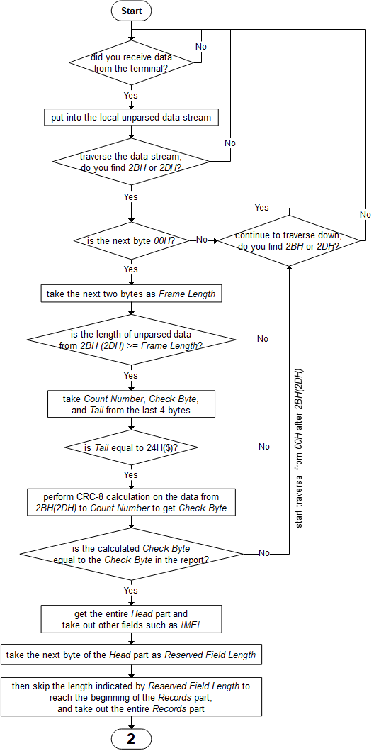
Please refer to the following flowchart to parse report:
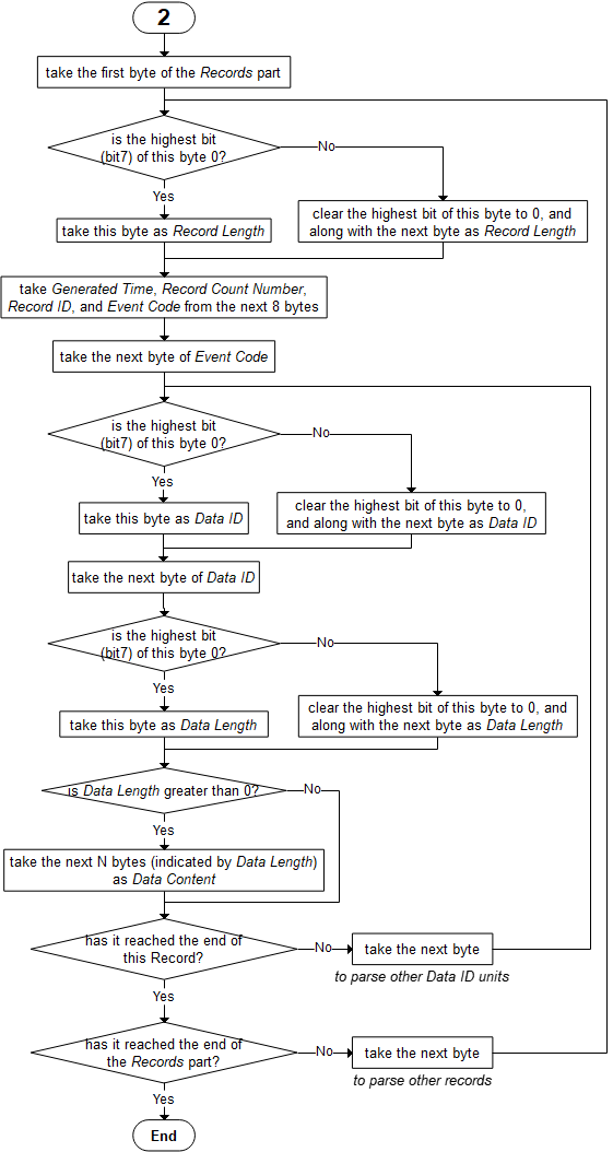
And refer to the following flowchart to parse the ‘Records’ part:
Here is an example of disassembling a report:
2B 00 00 4E 00 01 23 45 67 89 01 23 45 00 00 00 1B 00 00 37 64 F9 AA F6 00 00 03 00 02 0B 4D 79 49 6F 54 64 65 76 69 63 65 51 0F 09 07 3C 46 FF 01 DB 88 57 5F 17 9D A0 01 7D 55 0E 06 04 BC 8A 00 10 00 02 10 00 10 0C 13 03 01 23 4F 24
Total 78 bytes.
2B - Header ‘+’.
00 - Always be 00H.
00 4E - Frame Length, 004EH (78) bytes.
00 - 0b00000000, Multi-packet Flag is 0b0, indicating that there is no ‘Frame Count & Number’ field in this report.
01 23 45 67 89 01 23 45 - IMEI, “123456789012345”.
00 00 - Device Type, “0000”.
00 1B - Protocol Version, 001BH, means V27.
00 - Custom Version.
00 - Reserved Field Length, 0 means Reserved Field Data is absent.
Content of Record 03H:
37 - Record Length, this record has 37H (55) bytes. (Note: 37H=0b00110111, the highest bit is 0 means that ‘Record Length’ field occupies only 1 byte).
64 F9 AA F6 - Generated Time of this record. 64F9AAF6H (i.e., Timestamp 1694083830) means UTC time 2023-09-07 10:50:30.
00 00 - Record Count Number, 0000H.
03 - Record ID, 03H.
00 - Event Code, 00H.
Content of Data 02 (Device Name):
02 - Data ID, 02H (2), Device Name. (Note: 02H=0b00000010, the highest bit is 0 means that ‘Data ID’ field occupies only 1 byte).
0B - Length of content of Data 2, 0BH (11) bytes. (Note: 0BH=0b00001011, the highest bit is 0 means that this length field occupies only 1 byte).
4D 79 49 6F 54 64 65 76 69 63 65 - Device Name, “MyIoTdevice”.
Content of Data 81 (Mini Location):
51 - Data ID, 51H (81), Mini Location.
0F - Length of content of Data 81, 0FH (15) bytes.
09 - 0b00001001, Fix State is 0b10 (Fix), and Fix Mode is 0b01 (3D GNSS fix).
07 3C 46 FF - Longitude, 073C46FFH (i.e., 121390847) means east longitude 121.390847 degrees.
01 DB 88 57 - Latitude, 01DB8857H (i.e., 31164503) means north latitude 31.164503 degrees.
5F 17 9D A0 - UTC Time. Timestamp 1595383200.
01 7D - Speed. 017DH (i.e., 381) means speed 38.1 km/h.
Content of Data 85 (Registered Cell):
55 - Data ID, 55H (85), Registered Cell.
0E - Length of content of Data 85, 0EH (14) bytes.
06 04 BC 8A - PLMN is “310410”.
00 10 - LAC is “16”.
00 02 10 00 - Cell ID, 00021000H (135168).
10 - Access Technology & Roaming, 0b00010000, roaming status is home network (0b0) and access technology is LTE Cat-M1 (0b0010000=10H).
0C - Band, 0CH (12).
13 - CSQ RSSI, 13H (19).
03 - Bit Error Rate, 3% (03H).
01 23 - Count Number, 0123H (291).
4F - Check Byte, calculated by CRC-8 Calculation.
24 - Tail, “$”.